Todays, technology evolves in light speed and that has increasing impacts on high-speed interface in chips. Chips are vulnerable to external surges due to the decreased tolerance to ESD/EOS as the result of process miniaturization. Therefore, it is a challenge for IC design engineers to come up with a protection device up to such a threat.
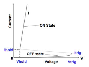
When we use an ESD protection device with the silicon controller rectifier, or SCR, its I-V curve has the snap-back characteristics, as shown in Fig. 1. This article will describe the SCR-based ESD device, the relationship between its I-V property and the latch-up effect, why the latch-up effect occurs and how to prevent it, so we do not choose the wrong TVS for lower clamping voltage.
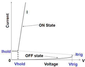
Figure 1. SCR TVS I-V curve
Definition of latch-up effect
For the latch-up effect, the protection device must be triggered ON by the induction voltage caused by ESD, surge or EMI. If the latch-up effect is triggered, the ESD device will still remain ON, even though the external surge may have already faded. This is what a typical latch-up effect looks like (Fig. 2).
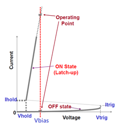
Figure 2. SCR TVS still ON
If external energy provides enough bias voltage (Vbias) and bias current (Ibias) to TVS, the device stays ON and will not be turned OFF. To stop the latch-up effect, the system must be de-energized, or something has to be done to make Vbias < Vhold or Ibias < Ihold. While the TVS stays ON at low voltage, large current will be directed to GND through TVS. In this case, the TVS will become hotter or even get burned. Another obvious impact is that the level of signal wire or power is clamped at low voltage because TVS remains ON, which prevents normal signal transmissions or keeps the power from reaching the normal voltage, resulting system error.
How to lower the risk of latch-up effect?
The constantly evolving CMOS process results in lower ESD tolerance of ICs than before, and that is why improving the clamping voltage (Vclamp) of external TVS device plays an increasingly important role. However, the TVS will expose to the high risk of latch-up effect if we make Vhold < Vbias just for the sake of lower clamping voltage (Fig. 3).
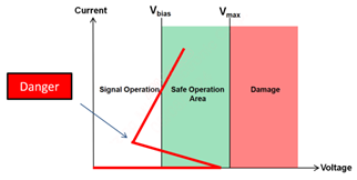
Figure 3. Vhold beyond the safe range of operations
It is shown in Fig. 4 that the safe range of TVS operations is between the voltage range of signal transmission (Vbias+10%) and the voltage range that leads to hardware damage at the rear-end ICs (Vmax).
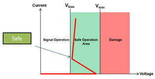
Figure 4. Vhold within the safe range of operations
If a load wire is used for latch-up evaluation, the risks of design schedule delay and incorrect choice of material may increase, because TVS’s Ihold varies widely with ambient temperature, and such an evaluation technique is not intuitive enough for system design engineers. What we do here at Amazing Microelectronic is to ensure that TVS’s Vhold is greater than VRWM in order to provide clients with TVS products free of the latch-up risk.
A case of latch-up effect
Re-timer or re-driver is frequently used in high-speed communication interface to improve the quality of signals. In this case, the client boosted HDMI1.4 signals with an HDMI re-timer to minimize jittering and amplify signals for greater flexibility in PCB signal wire length design. In HDMI applications, the signal wire is connected to power through a pull-up resistor. This way, the signal wire will have higher drive current. However, this source of current may become an important background factor of latch-up if the materials are selected not carefully enough for TVS products.
In this experiment, a client’s HDMI1.4 port for monitor is used for functional demonstration of latch-up effect, while an oscilloscope is used to observe the changes of voltage levels in IO signals. An ESD gun is used to discharge 1kV of static charge to HDMI port after it is confirmed that the system functions properly in BIOS mode, and the TVS located on the HDMI signal wire turns ON to protect the re-timer at downstream. Figure 5 shows that the monitor goes blank immediately after the 1kV ESD discharge, and the oscilloscope detects the voltage at which the TVS (not an Amazing Microelectronic product) is latched up. IT is seen clearly that the 2.8V normally shown drops to 1.8V, and the HDMI communications stop.
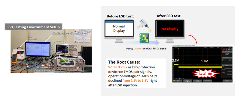
Figure 5. Latch-up effect caused by the incorrect selection of TVS
An automatic curve tracer, Tektronix 370A, is used to measure TVS’s I-V property under large current for analysis. It is found that the lowest voltage, Vhold, is 1.8V as the TVS enters the low-impedance conduction state, as shown in Fig. 6.
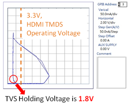
Figure 6. IV-curve of TVS with the risk of latch-up effect
A quick look at the technical data of the HGMI1.4 Re-timer reveals that the output voltage is 2.8V (with 2.6V the lowest), and the TVS Vhold that causes latch-up is only 1.8V. In addition, the short-circuit output current of HDMI re-timer can be as high as 50 mA on the signal wire, and the low-impedance path condition for IC output from short to GND is satisfied once the TVS is triggered into conduction by a surge. Such a current drive is enough to latch the TVS up for good.
At this point, the monitor display and voltage level will not be restored until the connector is disconnected to force de-energization of IC. The observation of current conduction for long time in this latch-up case reveals irreversible potential threats to ICs and TVS, such as burning down or drastically increased current leakage.
Therefore, Amazing Microelectronic recommends TVSs with VRWM≧3.3V for the protection of HDMI TMDS channels, such as AZ1143-04F for HMDI 1.4/2.0 and AZ1123-04F for HDMI 2.1, for both protection capability and system design safety.
Amazing Microelectronic promises to provide only products free of latch-up risks. We make sure that Vhold > VRWM on the design desk to eliminate any possibility of latch-up effect. A TVS without the risk of latch-up ensures the stable operations of system products.
Please contact the TOP-team to learn more about the portfolio of Amazing