February 13, 2024
The antennas for every wireless product provide the airborne interface for bi-directional communication with the outside world, and as such is actually the most critical element of the entire RF signal chain, providing both reception and transmission of all incoming and outgoing communications. With the term “Low Power” we are typically referring to portable or wearable wireless designs where power consumption is critical and optimised to provide the maximum battery life possible. However, in IoT this also includes many designs of static equipment designed to provide stable low power operation over many years.
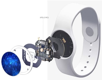
Figure 1: A typical wearable product, using an Ambiq Apollo SOC
In this article we consider the critical factors evolved in choosing a suitable antenna then consider how this can be tuned to specific product and the required use-case(s). We also take a look at the equipment required throughout the design, tuning and pre-certification processes.
In all low power designs, both transmit (TX) power and receive power (RX) are important considerations and in some designs, for example wearables, this represents a significant percentage of the entire products power budget. These criteria therefore need to be optimised to provide the correct level of performance for the given use case(s) so that the overall power requirements meet the budgeted battery life. Every aspect of the wireless performance and the entire wireless user experience are therefore reliant on consistent performance of the antenna in the huge range of all conceivable operating conditions. Achievable data rates are reliant on received signal strength as well as the amount of background noise and interference present, and since receive (RX) input sensitivities can reduce quite dramatically with progressively increasing data rates, this means that good antenna design and careful matching become more critical in order to achieve consistently high performance and a corresponding high-grade of user experience.
The success of modern low power wireless products is also tied to good antenna design, because this contributes significantly to a consistent user experience. Good antenna design provides the opportunity for higher data rates to be achievable and selected over longer distances and at the same time closes wireless links more robustly.
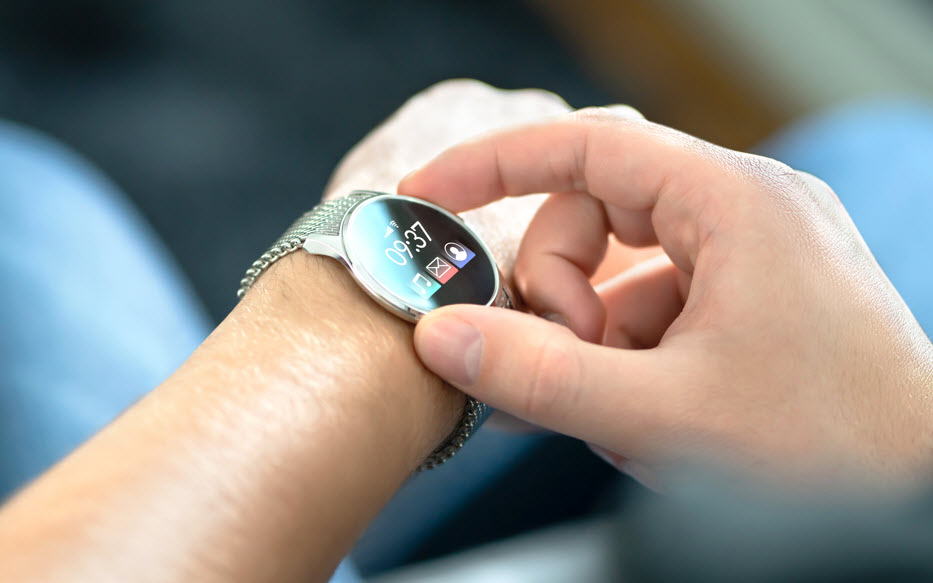
Figure 2, Wearables
Most portable and wearable consumer electronic designs have internally mounted antennas, or antennas designed to be an integral part of the housing, and in many of these cases antenna reference designs aren't a useful resource because they are never plug and play. This happens because antenna designs can’t take into account real-world factors concerning the physical design and materials utilised in the product, all of which change the antenna design and tuning. Proximity to the body also changes antenna design considerably and needs to be taken into consideration within the design and matching. We will return to this aspect later and discuss products and equipment to be able to manage these challenges and provide good antenna performance.
In the absence of external interference, a well-designed antenna maximises signal level while minimising reception of noise. With Tx and Rx antenna gain the effective gain is doubled - increasing the signal to noise ratio (SNR) and helping achieve good performance within and to the edge of the link budget. The huge commercial success of unlicenced communications has both driven the technology forward and also driven up noise considerably in the ISM 2.4GHz band, leading to the requirement to expand first into the 5 GHz and now into the 6 GHz midband channels, taking larger allocations of bandwidth for the new services and bands.
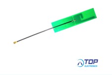
Figure 3: Adhesive Antenna
Despite these positive developments the 80MHz or so of bandwidth available at 2.4GHz remains highly over-subscribed, and especially in urban areas, the consequent channel noise interference is often very significant. This noise reduces transmit distances dramatically because when the desired signal and the noise in the channel from other devices become similar orders of magnitude, the interference will progressively disable reliable communications for the desired received signal. For bidirectional communications this happens at both of the received channels for each of the signal paths at the same time, shortening transmit distances considerably.
The noise floor of the 2.4GHz band must be managed by many other equipment’s operating and sharing the band, such as Bluetooth, Zigbee and Wi-Fi. Nowadays, more than ever, all the interoperability protocols have to be specifically engineered to provide reliable communications despite the presence of this noise.
Another important consideration is that since we cannot predict the position or polarisation of such noise sources, it is normally desirable that low power devices have an antenna that provides equal performance in all directions such that a specific orientation does not provide significant changes in performance.
The user experience is heavily tied to providing consistent performance in the range of orientations and operating conditions. Figure 3 shows an Adhesive Antenna that is pre-tuned and optimised for mounting on the inside of a plastic enclosure.
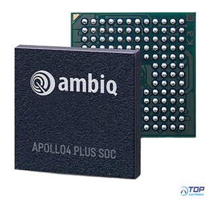
Figure 4: Ambiq Apollo 4 SOC with BlueTooth
TOP-electronics also distributes the Ambiq range of BlueTooth enabled SOC’s (System on a chip's). These devices are optimised for low power radio design and use sub threshold technology (SPOT) to run their processor cores and associated sub-processors at voltages much lower than used on traditional designs. Traditional CMOS designs typically use core voltages of around 1.2v, whilst Ambiq uses only a fraction of this value, with a typical resulting multiplier of around 10x savings in power compared to the lowest power CMOS device providing similar levels of compute performance.
The Apollo4 series includes an Arm M4F Performance Core running at up to 192 MHz plus a dedicated Arm M0 core for Bluetooth communications as well as a built-in floating-point and graphics acceleration. Ambiq has the lowest power per MHz available on the market for the given compute power, and their devices are now deployed extensively in the latest smart watches and wearables from many of the leading brands.
Wearables are particularly of interest because they combine the largest simultaneous number of design challenges to be managed. They have to be engineered to be as physically small as possible, whilst providing the highest level of user experience and longest battery life. In addition to these challenges, there are typically many other components that need to be considered in terms of antenna design including metallic elements as well as the LCD, touch screen and battery.

Figure 5, The future of wearables with AR
One of the additional challenges with wearables is that losses around the body are often unpredictable and change dramatically depending on the physical environment and noise floor. Closing links around the body is not as easy as one would imagine because there is a wide difference in the attenuation characteristics that is entirely dependent on the two communicating device positions and surroundings. Curiously, closing a link from the front of the body to the back is one of the most challenging conditions because it is difficult to determine the power requirements.
In outdoors environments there are less reflective surfaces to rely on, but normally the noise floor is also lower which often helps to compensate because there is less interference from other devices. Some of the most difficult use cases for portable low-power radio devices are environments such as public concerts and densely-packed trade-shows where there are simultaneously a large number of people in close proximity and a large number of devices competing for radio bandwidth.
Some low-power devices fail completely to operate under these conditions hence, these use cases need careful consideration within the antenna design so that devices continue to function with as many environmental challenges as possible.
A critical parameter for reliable communications is link budget which can be calculated with the simplified example below (Equation and Figure 6):
Rx power (dBm) = Tx power (dBm) – Tx feed loss (dB) + Tx antenna gain (dB) – path loss (dB) + Rx antenna gain (dB) – Rx feed loss (dB)
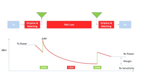
Figure 6: Path Loss & Link Budget Margin
We can also calculate the received signal and then compare it to the background ambient noise level, providing a signal to noise ratio (SNR). Assuming the received signal is sufficiently above the SNR, it will be successfully received. When the noise floor becomes too great the signal will drop out during operation or the devices will fail completely to communicate.
From the equation above, it is clear that it is a good idea to augment the elements that have a positive effect on the received signals (Rx antenna gain, Tx antenna gain and Tx power) and also to reduce the unwanted factors (Tx feed loss, propagation loss, and Rx feed loss). Whilst we can’t affect changes in the noise floor of the environment, a very useful engineering task is to ensure that the Rx antenna is located so as to maximise reception of the desired incoming signals and to minimise any noise reception coming from other parts of the product to thereby achieve the maximum channel SNR available.
Propagation losses are dependent on the distances between the Tx and Rx, but are also a function of the materials the signal must pass through, or reflect/disperse off. Hence it is also important to consider how other components making up the product might affect antenna performance placement or signal propagation. There are design tools available to be able to model these aspects.
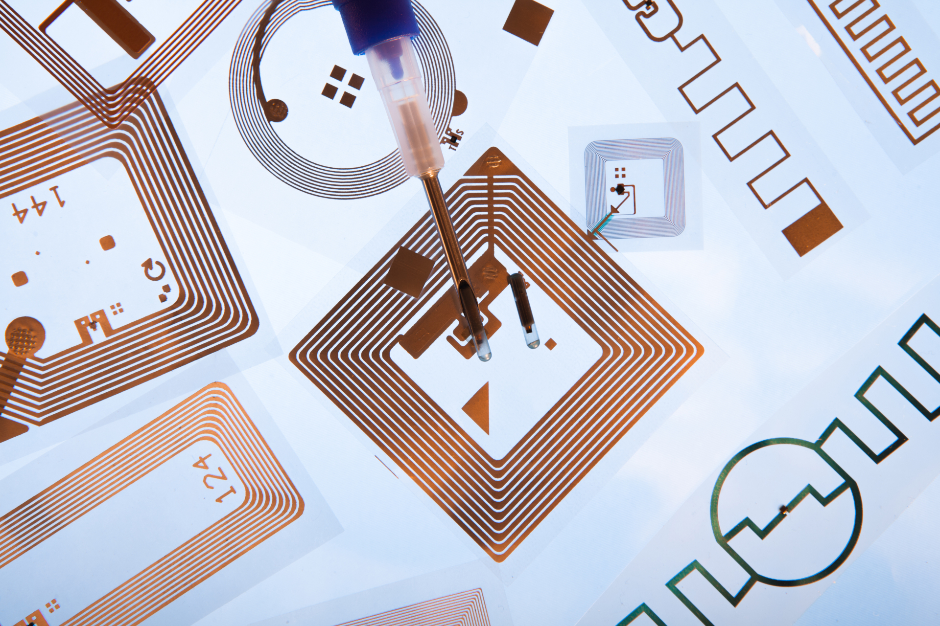
Figure 7, Printed Antennas
On the transmit side, radiated energy from the antenna depends heavily on antenna tuning for the frequencies used. When an antenna is not correctly matched or tuned, a percentage of the transmit power gets reflected back into the transmitter rather than being radiated out by the antenna. This is undesirable as this energy is wasted as heat and does not help the system to meet the link budget goals. Both the choice and design of antenna for a desired frequency range as well as the tuning are both important to maximise the output power and avoid waisted reflected energy.
The simplest form of theoretical antenna is the isotropic radiator. This is a theoretical antenna that radiates power perfectly evenly in all directions. The so called “antenna pattern” represents the actual shape for how a practical antenna signal radiates. For the perfect isotropic radiator, the orientation of the transmitter is irrelevant as the signal will be radiated evenly. No antenna however radiates energy consistently in all directions. They all radiate energy slightly unevenly, with more energy being transmitted/received in certain directions and less in others.
In fixed applications this is often used to maximise the gain in a particular direction, for example point-to-point microware links often use highly directional parabolic or patch antennas to focus the power in a single direction. This is done to meet the link budget with minimum power, whilst reducing the risk of interference to other services.
For most low power wireless products, the orientation of devices is constantly changing, hence the ideal radiator is perfectly omni directional for both TX and RX. Whilst the perfectly ideal isotropic radiator does not exist, we generally strive in low power wireless products to have the antennas as omnidirectional as possible to provide more consistent performance and user experience.
An aspect that could possibly help in future is Transmit Power Control (TPC), where transmit power is dynamically controlled to close bidirectional links. Although more complex to manage, there are two important motivations for these techniques to become more accepted.
Firstly, it enables significant power savings to be accomplished, but also it reduces enormously the amount of stray unused RF energy radiated into the environment. Unused RF energy achieves nothing useful, wasting battery energy in portables and increasing the entire interference noise floor in the channel, driving up power for other users to overcome the interference, which in turn drives even more noise into the channel. This is analogous to the same process that occurs in a busy restaurant when everybody is obliged to talk more loudly in order to be able to communicate above the ambient noise.
It is quite possible in a number of years, that regulatory agencies and bodies start to mandate TPC for certain use cases in order to harness more useful spectrum. One of the principal motivations for taking such measures would be to allow for greater spectrum sharing. There is pressure internationally to allow greater sharing of both unlicensed and licensed spectrum resources as the globe becomes more connected and more services need to co-exist and work together in the same bands. Mid band spectrum in the region of 3.1 – 7.5 GHz remains in very high demand and spectrum sharing is seen as one possible way to accommodate this.
With a similar goal, beam forming could also become much more popular for certain consumer applications, for example wireless routers, because it could allow dynamically focussed RF energy in a specific direction. This can become useful for the ever-evolving high-QAM high bandwidth Wi-Fi applications. These devices could possibly benefit in the future from dynamically focussed power because the sensitivity of the receiver is reduced at the higher QAM values. Beam forming also saves power and reduces interference from other devices because the RF energy is arranged to be focussed on the communicating devices.
There are a number of critical questions to address when choosing or designing an antenna solution that change dramatically what type of antenna is required, and what type of tuning steps are necessary.
The number of factors that need to be modelled, designed and balanced increases dramatically with the compact form factor of wearable devices. The amount of engineering design that goes into products of this type can be very considerable, corresponding to the increased number of engineering challenges.
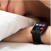
Figure 8: Wearable Medical Device
PCB antennas appear attractive from the point of view of being cheap but can be expensive in design resources and also require correct placement and shielding to prevent unwanted PCB traces becoming unintentional radiators. In production, there are challenges associated with controlling and testing the PCB characteristics over different production lots and layer thicknesses to ensure consistent RF performance.
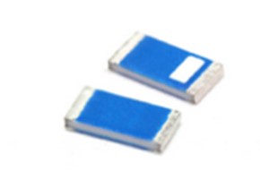
Figure 9: Chip Antennas
TOP-electronics distributes chip antennas from Summit Electronics, 2J Antennas and other manufacturers. These types of products are useful being physically small simple to use. They offer a straightforward set of design requirements and tuning steps for reliable operation in many designs. TOP also carries adhesive, PCB, and trace antennas from Summit Electronics, 2J Antennas and Quectel. These antennas offer good performance and slightly higher gain, but with larger footprints.
Certain enclosure materials for example metal, pose more engineering challenges due to reflection than other materials like plastic, epoxy or ceramic (which dependent on proximity, also shift the centre frequency of antennas).
All these characteristics need to be taken into consideration when considering the antenna, tuning it and combining the physical design elements of the product.
In grossly simplified terms, a relationship exists between the number of design challenges to be managed and the amount of space available for a given radio design. To a point (and dependent on frequency) the more real-estate space you have the more the physical separation can be used to isolate sensitive parts of the circuit from other radiators.
The more compact a design has to be, the greater the number of design challenges that have to be solved to achieve target performance and operation for the chosen use cases. With highly compact designs extensive RF modelling of the entire system is advantageous.
Certain radio environments can be noisy from an interference perspective and such noise is nearly always completely invisible from a consumer’s perspective. For example, with dense urban environments, the interference indoors can be very considerable within the ISM bands. How a given product manages these ‘everyday’ challenges is important to its acceptance because consumers expect consistent performance without having knowledge of such environmental operating conditions.
Good RF design is always apparent because consumers are used to the performance of the best devices they own and these become benchmarks during everyday operation, with new devices being compared to devices they have owned for a while.
Based on the constraints of the product design, one can define the type and size of antenna that is required. After selecting a suitable antenna, almost all designs require a tuning step.
TOP-electronics also distributes MegiQ that make professional and affordable RF development tools for design and tuning. The product range includes Vector Network Analysers (VNA’s), which differ from traditional Network Analysers because Scalar Network Analysers only measure the amplitude of the test signal while Vector Network Analysers measure both the amplitude and phase.
This vector measurement allows for matching circuits to be easily calculated for the purpose of antenna tuning. VNA’s have become more popular nowadays, and the pricing levels have become more attractive due to the increased volumes.
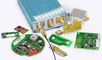
Figure 10: Megiq VNA Products
MegiQ also produces a VNA product with a bias generator output port, allowing the user to send a signal to their RF circuit, permitting measurement of more complex RF circuitries.
The software supplied with these products has an integrated Match Circuit Calculator that calculates multiple suitable matching circuits for a given antenna solution and displays the result interactively. You can therefore actually see in real-time how the matching component values change for a given antenna solution when the antenna is in close proximity to the body. This function is shown in the videos available here: https://www.youtube.com/watch?v=AhzVqnHn0is
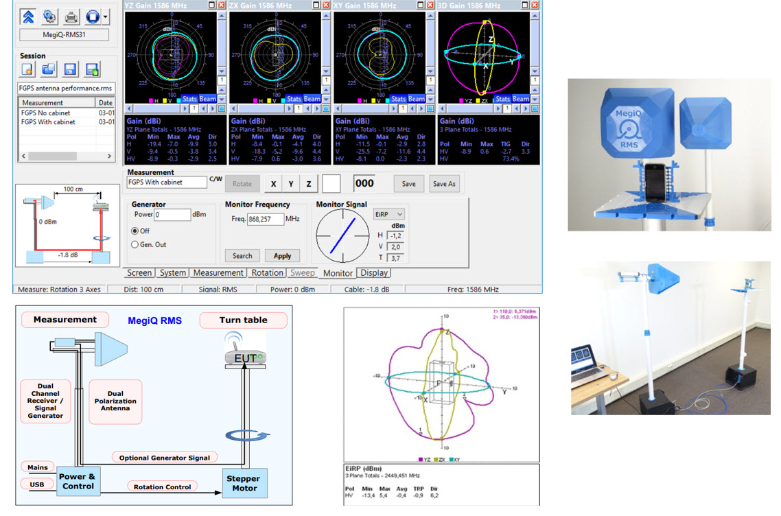
Figure 11: Megiq Radiation Measurement System
In addition to the VNA products, MegiQ also produces a Radiation Measurement System, which provides measurement of antenna radiation patterns and is designed to be used without Anechoic chamber and also within Anechoic chambers. Top and MegiQ provide guides on room setup for optimised operation and placement inside normal room conditions to limit the number of reflections. With good setup one can get a very close representation of the device’s radiation pattern. This is extremely helpful in antenna design and placement. Being able to perform these kinds of tests and measurements in-house allows for the possibility to debug antenna designs rapidly without the considerable capital outlay of hiring an anechoic chamber each time for development testing.
The last steps before product launch are product validation and certification. Sometimes for the certification process there is an additional final tuning step required.
Conclusions:
Low power wireless products are heavily reliant on good antenna design because the available power is always limited. This has a corresponding effect on available link budget and range defined by what is actually possible. Reflected energy due to tuning issues is particularly undesirable when every fraction of a milliwatt counts.
Consumer awareness of engineering challenges is limited, including the amount of interference noise present due to extensive proliferation of ISM Band devices sharing the band. This has changed dramatically the maximum available SNR, yet customers always demand more, leading to massive investment and innovation to help manage these issues.
Leading companies in the wireless market spend huge resources to develop wearable products which are optimised for power consumption and performance which become baseline references for how every product should perform with a hugely challenging set of operating conditions.
The success of a given product therefore becomes heavily reliant on antenna design and on achieving consistent performance over a large number of environmental factors which are uncontrollable and invisible to the consumer. What a glorious engineering challenge!
Consequently, antenna design is considered fundamental to the design brief for consumer devices and nearly always now considered from day 1 of conception to product release. Antenna reference designs are nearly always not useful because real-world factors cannot be factored into generic antenna designs. Some consumer products deploy multiple antennas tuned to different body proximity locations and select multiple antennas dependant on operating conditions to provide consistently optimised user experience and performance.
Wearables combine the largest number of simultaneous design challenges. In addition, their operating conditions are far from simple due to the unpredictable behaviour of radios worn around the body. Every material of every component in such designs is important for consideration of radio performance. These are taken into consideration with increasing detail due to the evolving computational power and more advanced modelling tools available.
Sub threshold CMOS will likely become the norm in time for wearable product design in the future. It is possible that Transmit Power Control (TPC) becomes more accepted and it could even become mandated in the future for certain use cases to enable greater sharing and band re-use. Beam forming could also be used to augment the drive for more and more wireless bandwidth in the home environment by proving focussed links.
Product specification and it’s intended use cases always helps defines the approach required for the antenna. Physical space limitations issues in low power wearables, portables and other compact RF designs can be overcome by greater design with smaller shielding components, more extensive modelling and availability of advanced measurement equipment designed to provide good results without the need for anechoic chambers.
For more information on availability and options please reach out to TOP-electronics at
Back